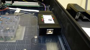
I had to program PIC28F8722 micro controller at ICT test station. I found a solution for less than $300. and some custom fixture designs. The main board design must have a 5 pins header which has ICT test points. MCLR, DATA, SCLK, GND, VCC.
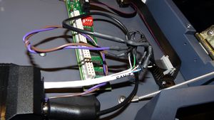
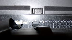
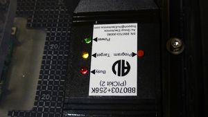
I found a PIC program to go on the internet for $200 including shipping. This box can be loaded with our firmware in hex using a usb port and programs the board under test through these 5 pin header. This box is designed to manually program each board, therefore, it has the program button on it. There are 3 LEDs to show the status of the process, program, idle, power on. To automate this box through ICT test plan, I need to wire power, program button, all LEDs to the fixture for complet automatic testing without operator interaction.
[non-members]please log in to continue reading… Thanks[/non-members][members]
In order to detect the LED states for 3 LEDs, we need to write a few custom digital tests to detect the conditions of the status. First, check out all the condition of these LEDs and name the test accordingly, notice the blinking frequencies so we can set the vector cycle. Dependent upon the status, we need to set the vectors correctly.
Green on steady – Yellow blinking – Red is OFF (condition)
sequential
receive delay 1.4m
vector cycle 1.5m……
unit “On_blink_off”
repeat 50 times !!Make sure Green is on-Red is off
execute Green_1
execute Red_0
end repeathomingloop 500 times !!Detect Yellow 0ff
execute Green_1
execute Red_0execute Yello_0 exit if pass
end homingloophomingloop 500 times !!Detect Yellow on
execute Green_1
execute Red_0execute Yello_1 exit if pass
end homingloophomingloop 500 times !!Detect Yellow 0ff
execute Green_1
execute Red_0execute Yello_0 exit if pass
end homingloopend unit
So if this test pass, then that condition is met, we can proceed with the next command according to the programming procedure. Write all the conditions and put in the testplan in a subroutine to execute sequentially as needed.
This is the old subroutine without LEDs detection tests, must have operator interactions.
input “Are Green LED ON (steady), Yellow LED blinking, Red is off? If they are, Please Press Enter”,Pic$ !! So we need a test to detect this.
if Pic$=”” then
wait 1
gpconnect 20648 to 20649
wait 1
gpdisconnect 20648 from 20649
end if
input “Are RED & GREEN ON and YELLOW is OFF? Please Press Enter for YES (wait 50 secs) and type n for NO”,Pic$ !! So we need another test to detect this.
if Pic$=”n” then
print tab(5);”Please Check U4 and Power connection”
fail device
print tab(5);”Please Check U4 and retest”
report “u4 is not programmed”
else
wait 25
end if
input “Are Green LED ON (steady), Yellow LED blinking, Red is OFF? Please Press Enter for YES and Type n for NO”,Pass1$
if Pass1$=”” then
print tab(5); “PIC18F8722 is Programmed”
report “PIC is Programmed”Make sure when we program the PIC, use the board power to turn on the PIC and NOT the programming box. Also when program the ROM, select checksum verify.
[/members]


1 Comment
i have seen that some engineers detect voltage of the leds of the programmer.