
I helped someone to install FBAS on his 4E0 035 729 – 8/17/2016
-
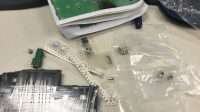
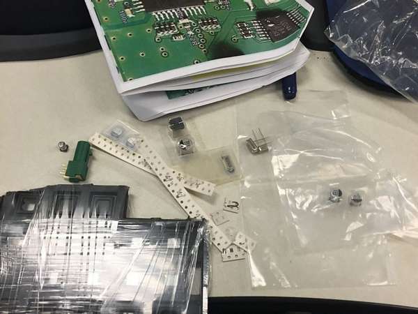
- Getting Parts Together
-
- FBAS circuit Unpopulated Top

-
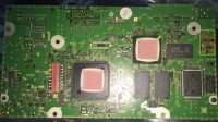
- FBAS circuit Unpopulated Bottom

-
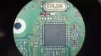
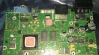
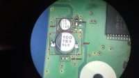
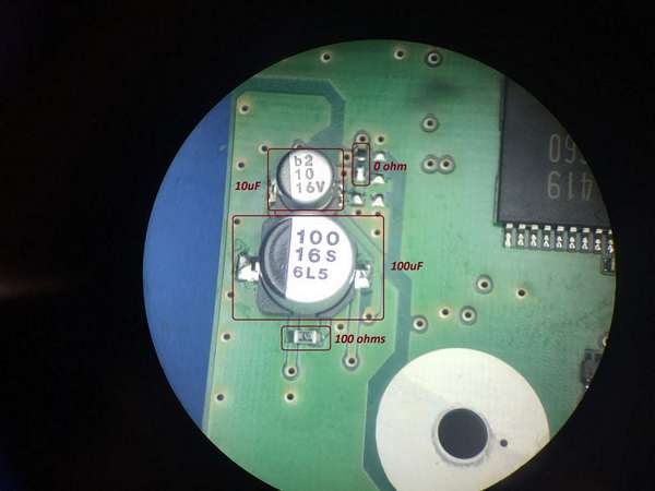
- FBAS NXP circuit populated

-
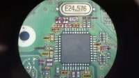
- Video IC NXP Populated with 24.576Mhz Crystal
-
- FBAS connector Resistors

-
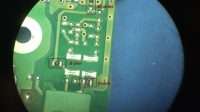
- The other side of FBAS circuit
-
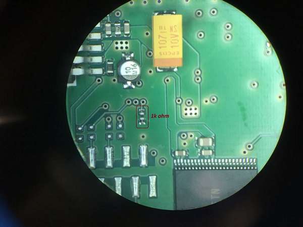
- 1k ohm resistor location
-
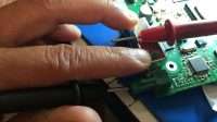
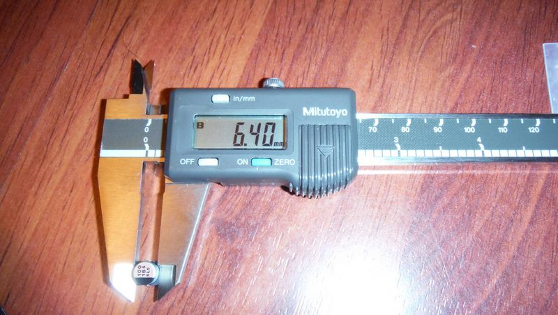
- Measure FBAS input to ground
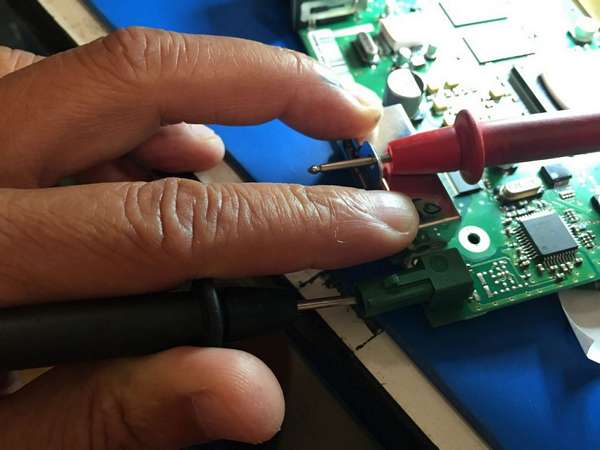
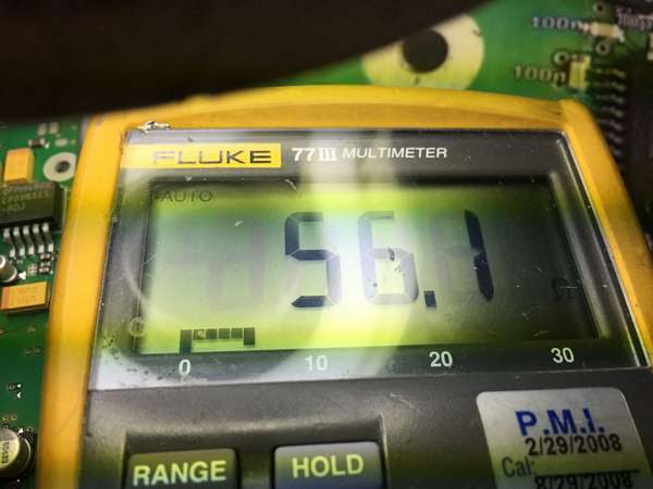
-
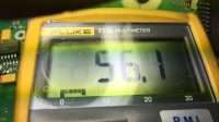
- 56ohm between FBAS input to ground
-
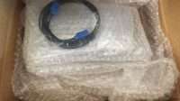
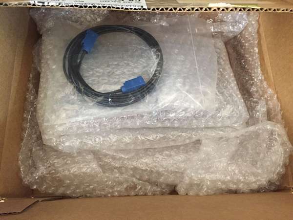
- Package the board with cable
-

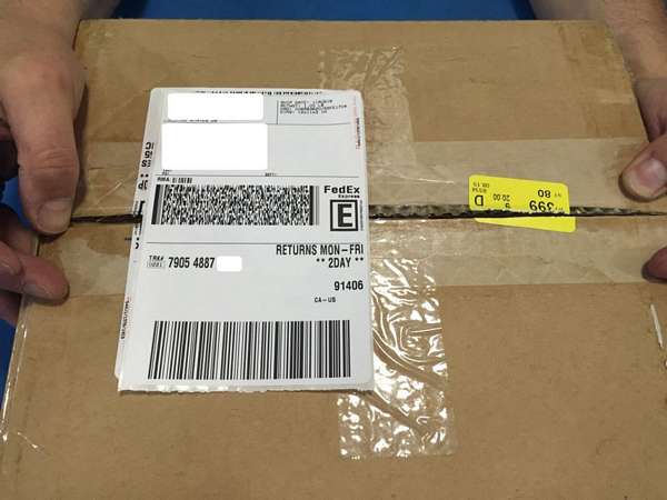
- Return package
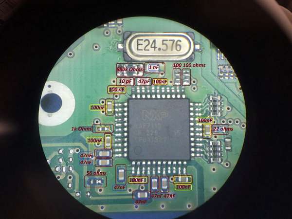
2013-06-07 Parts needed to add to the board – 4E0 035 729 to make 4E0 035 729 A.
All parts should be size 0603 – SMD
Capacitors = 7 x 100 nF, 6 x 47 nF, 1 x 10 pF, 1 x 47 pF, 1 x 1 nF.
Capacitors electrolytic = Size 1 – 1 x 10uF, Size 2 – 1 x 100 uF. The surface mount pads are almost the same distance as the diameter.
Resistors = 1 x 56 ohms, 3 x 0 ohms (can be shorts), 1 x 22 ohms, 3 x 100 ohms, 2 x 1000 ohms, size 0805 or 1206 1 x 680K (680,000) ohms.
Crystal = 24.576 Mhz SMD or through hole.
I
still have one extra set of these– email me if you’re interested – $30 + shipping (US only) if in Europe contact Kris at VNSMedia to buy.

All Audi A8 from 04-06 don’t have RVC camera as an option. Unless the car has the TV or DVD options, the MMI Head Unit may not have the FBAS for the video input from the Camera. This Head Unit part number for A8 is 4E0 035 729 without FBAS, with FBAS, the part number will have “A” in the end 4E0 035 729 A.
I’m pursuing the RVC (rear view camera) retrofit for my 06 A8, my Head Unit doesn’t have an A, it’s missing FBAS circuit which I have to add for video receiving input. There is a company in Poland that offer to add the whole circuit for a fee, we just have to send the box over to them and wait to receive it back. We can also buy a unit that’s from another car, but the problem is that we will have to take it to the dealer to remove “component protection” because every car is built with specific components to specific id number. When we change something, we need to notify the “mother ship” = Audi center. Therefore, if we modify the existing circuit, we won’t have “CP (component protection)”.
According the expert in Poland, to add a workable circuit for FBAS, we will need all the components on the picture. It’s hard to see what size of components we need on the pictures, but all CAPACITORS & RESISTORS use size 603 SMD. The can electrolytic capacitor use size 1 (10uF) and size 2 (100uF) surface mount.
All these components are designed into support SAF7113H.


Parts readily available in the US are all components except 2 that I have to order for China – The 9-bit video processor SAF7113H and the Fakra male connector “E”. I also ordered 5M Fakra cable from China, but many people order from Kufatec in Germany which is custom made for specific cars like Audi.
If you are in Silicon Valley, Halted.com sells everything we need for this project – capacitors are $.02-.04 – resistors $.06-.08. 24.576MHz crystal (metal surface mount) = $.87. The cost of retrofitting this board is $15 for SAF7113H from China and $4. for the connector FAKRA. all others are less than $10.00. We do need T8 to remove the board from the case. Harbor freight sells a nice set for $8.


The case will have to be drilled and sawed a part for the Fakra “E” connector to go through.


93 Comments
Hi,
can you tell me something about the parts on the third picture right above the connector (I think it is a picture from an original -A device?)
These parts are not mentiont in any instructions I found. It looks like a protection circuit so it is not really necessary but it would be nice to know more about this.
The 18ohm resistors are used for termination of the signal lines (to reduce reflections) but 0ohms are ok, too. This is not as important for these signals.
The 10uH with the 1nF are used to assist the quartz at startup, the 680k insteat will do the same (and is a few cent cheaper).
Hello Micha,
I think you’re talking about the original circuit board – I believe the input of FBAS is filtered or buffered by this circuit – I wanted to implement the whole original circuit, but I don’t know the IC in the circuit – The picture is not clear enough, also, the big 2 capacitors (values?). I was going to pull the MMI from the Q7 to look for the marking on the 5-pins IC and measure those bias caps and resistors but my wife didn’t let me to tear down the Q7. If you look on the left, it’s by pass the whole circuit with jumper. As I understand and ohm it out, there are 4 video inputs, but FBAS only goes into 1 input, I think it’s pin 43, the muxing for all videos inputs is from the Back Up camera controller. If you can find out the components of the original circuit, please let me know. Now, I noticed the difference between this FBAS implementation and the original Q7, Q7 seems to switch video lines very quickly, the FBAS retrofit, flicker once and switch. Other than that, the quality is the same. Again, my camera is a $20 after market Sony CCD (supposed to be great) which works great in the day time, but very grainy (noises) at night while the original Q7 is very clear.
Thanks for your reply, I had the same problem with the picture but I’ll have a closer look at the wires on my PCB when I modify it.
Hopefully I can find out something more, then I’ll let you know.
I’m going to buy the Kufatec set with the original cam here in Germany and after I’ve finished with the retrofit, I’ll try to compare it with the original -A Head Unit. I’ll tell you if there is a differece in switching speed or flickering, too.