
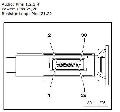
For those who have older Audi with AMI (Audi Music Interface) unit installed, we tend to get stuck with a 30-pin iPod and iPhone original AMI cables. There are many part numbers for each type and year of the car, but by playing and modifying AMI cables, I found out that they’re basically the same, the only thing different is the resistors detection. All 3G cables have detection resistor (pin21 & pin22) ~18.7k and 2G ~ 1.87k. When the resistor detection is less than 900 ohm – 0 ohm, the AMI changes to Auxiliary mode which will turn off the USB power and play whatever on pins 1,2 with ground 3. By design, the resistor detection will go to Auxiliary mode with value of 1k ohms for all version. .
To make an external USB drive connector.
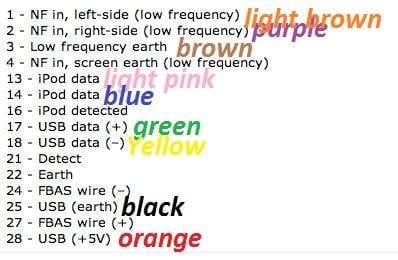
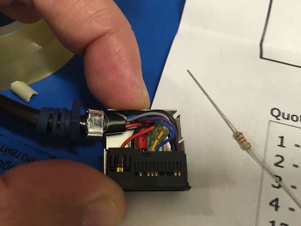
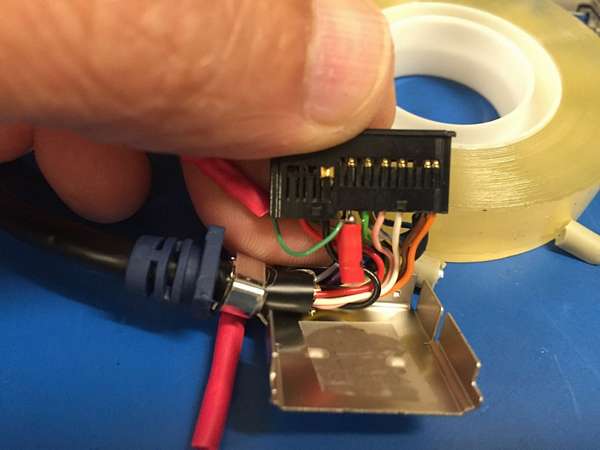
We need to get a female USB connector and wired it to the AMI connector with correct pins and designation: pin 28 (orange) = 5V, pin 25 (black) = Ground, pin 17 (green) = USB data +, pin 18 (yellow) = USB data -.

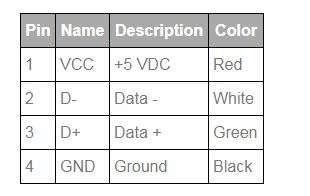
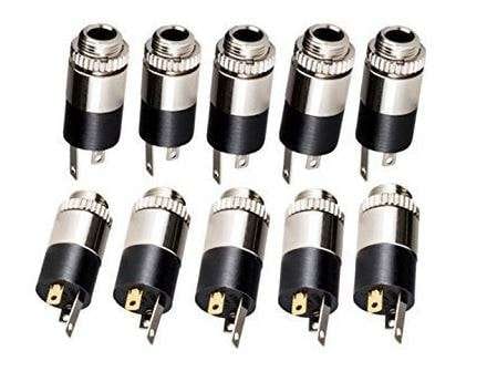
To make an Auxiliary Female Connector.
We need a female 3.5 mm jack connector: pin 1 (light brown) to left, pin 2 (purple) to right, and pin 3 (dark brown) to ground. It doesn’t really matter which pin 1 or 2 is left or right, as long as pin 3 is to ground.
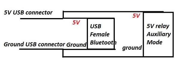
To make a USB female power cable for USB dongle and relay (auxiliary mode) power when plugged in.
Get a female to male USB extension or a bulk female, but it’s better to get the extension an try to splice out the 5V and Ground line for the relay.

17 Comments
Hi
recently I tried to make a AMI-RCA cable, which consists of 18.7K on pin 21-20 as detection and AUDIO(3 pins)+ FBAS(2 pins), but it didn’t work, not detection and no video out to MMI-2G high screen.
I am afraid this should need the video decoding chip you have soldered manually in another blog, right?
Any comments?
Regards
All video must go through TV tuner and FBAS connector on the MMI Head Unit. It doesn’t work using the AMI connector. I tried it and it didn’t work either.
Hi iDog.
Just wanted to thank you for all the info! You helped me out quite a bit. I’ve got a 2014 Audi A4 with AMI in the glove box and the standard Concert head unit. Wanted an AUX cable but where i’m from they are very hard to find.
So I took a big jump and removed the AMI unit from the glove box and opened it up. I managed to trace the pins according to your post and soldered an input jack directly to the pcb and a 1k resistor on the detection pins and boom! It works awesome!
Although I know I wont be able to use the AMI for anything else, AUX is all I need. Will be getting a propper bluetooth reciever that works on 5V and use the 5V pins on the pcb to supply the bluetooth reciever then I can finally after 3 years have good quality A2DP audio streaming!!
Thanx again for all yout efforts. Will follow your page. Keep up the good work!
You can add the fbas pins to rca video connector and add CarPlay
Please elaborate further on this.